- Contact us
- |
- About us
- |
- |
-
- Personal information
- Organization
- Quotes
- Address book
- Login
- Don't have an account? Sign-up
Compact high performance power line filter for shielded rooms
- Home
- EMI - EMP power, signal & data line filters
- Power line filters
- Compact high performance power line filter for shielded rooms
The Compact high-performance power line filters are capable of providing a radiated transmission loss of 100 dB at 14 kHz up to 40 GHz. The leakage current is in milliampere level and the voltage drop is less than 1 V.
The filter is made to withstand the harshest environment and is very economical. Because of the custom design for your own filter, the assembly is very simple and always with very low leakage. This filter is also a stock item and therefore always available quickly.
This series is offered as a two-line filter (single-phase and neutral) or as a four-line filter (three phases and neutral). The single-phase filter can withstand up to 277 Volt, 1-1000 amp. If you are looking for a filter that can withstand more power we have the three-phase filter, this filter delivers up to 480 Volt, 1-1600 amp. The neutral line is always attenuated and all conductors are decoupled from each other. This allows the conductors to operate independently without attenuation loss.
The circuit is designed as a symmetrical double-circuit with high-quality rod cores providing inductance. These cores do not saturate due to their large air gap and they are insensitive to asymmetrical load.
Foil capacitors ensure a long operating life by their self-healing features even after voltage transients. A seamless fixing of the filter casing to the shielded room is very important to ensure the correct operation. The filter is housed in a casing that has a base flange which provides stable mounting and excellent earthing when bolted to the shielded room via the mounting bolts.
Please note: EMP protection is available on request.
Also, check our Ultra high-performance filters
Technical data
| Rated voltage VR for two-line filters | 277 VAC/500 VDC | line-line or line-case |
|---|---|---|
| Rated voltage VR for four-line filters | 480 VAC/277 VAC | line-line line-case |
| Rated Frequency fR | DC -60 Hz | |
| Rated Current IR | See characteristics | Referred to +40 °C ambient temperature |
| Number of lines | 2/4 | |
| Test voltage | 1200 VDC / 2 s | Line-line or line-case |
| Voltage drop/phase ΔV | <1% | of VR at 50 Hz and IR |
| Leakage current I Leakage | See characteristics | at 250 VAC and 50 Hz |
| Reactive current I Reactive | See characteristics | at 250 VAC and 50 Hz |
| Discharge Time to Below 34 V | 30 s | |
| Climatic category | 25/085/21 | |
| Shielding performance | 100 dB @ | 14 kHz ~ 40 GHz |
Advantages
- Applicable in very low frequency (VLF) applications
- Can be delivered EMP-proof
- Suitable for use under extreme conditions (military applications)
- Wear-resistant
- Insensitive to corrosion
- Shielding performance: 100 dB @ 14 kHz-40 GHz (MIL-STD-285)
Applications
- Shielded rooms
- Shielded chambers
- Anechoic chambers
- Military applications
- Medical applications
Mounting
These protections are designed for mounting on the penetration panel or directly on the non-painted wall of the Faraday cage. Mounting terminals are dependent on the amount of power. Please see Connection in the Product range table.
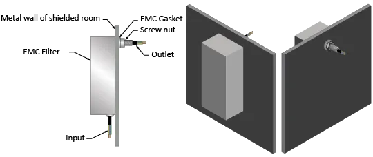
Installation diagram
The technical drawing below shows how a power line filter is mounted on the wall of your Faraday cage.
Insertion loss
Please note: These values are measured under laboratory conditions. Results may vary in other situations; please read our Guarantee
Available dimensions
Single-phase and neutral filter types:
277 VAC/500 VDC, 1-1000 amp
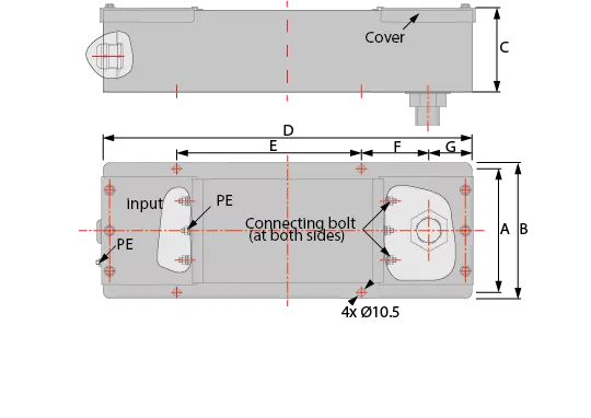
Outline drawing 1
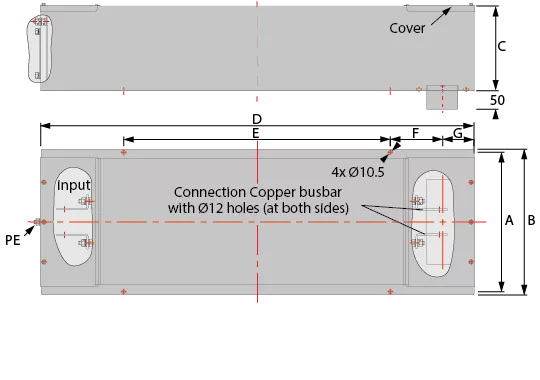
Outline drawing 2
| Type | A | B | C | D | E | F | G | Installation instructions | Outline drawing | IR (A) | I Leakage (A)* | I Reactive (A) | Terminal connection | Shielding Effectiveness (dB) | ||
|---|---|---|---|---|---|---|---|---|---|---|---|---|---|---|---|---|
| In | Out | |||||||||||||||
| 8020-2-16 | 188 | 205 | 120 | 750 | 450 | 110 | 80 | M24 conduit screw | 1 | 2 × 16 | 0.02 | 1.7 | M6 Screw | M6 Screw | 100 dB, 14 kHz ~ 40 GHz |
|
| 8020-2-32 | 188 | 205 | 120 | 750 | 450 | 110 | 80 | M24 conduit screw | 1 | 2 × 32 | 0.02 | 1.7 | M6 Screw | M6 Screw | ||
| 8020-2-63 | 188 | 205 | 140 | 920 | 620 | 110 | 80 | M33 conduit screw | 1 | 2 × 63 | 0.02 | 1.7 | M6 Screw | M6 Screw | ||
| 8020-2-100 | 228 | 245 | 155 | 960 | 450 | 205 | 80 | M60 conduit screw | 1 | 2 x 100 | 0.15 | 7.0 | M12 Screw | M12 Screw | ||
| 8020-2-200 | 228 | 245 | 155 | 960 | 450 | 205 | 80 | M60 conduit screw | 1 | 2 × 200 | 0.15 | 7.0 | M12 Screw | M12 Screw | ||
| 8020-2-250 | 228 | 245 | 155 | 960 | 450 | 205 | 80 | M60 conduit screw | 1 | 2 × 250 | 0.15 | 7.0 | M12 Screw | M12 Screw | ||
| 8020-2-400 | 320 | 340 | 205 | 1360 | 850 | 170 | 120 | 2 | 2 × 400 | 0.30 | 7.0 | Busbar | Busbar | |||
| 8020-2-630 | 370 | 390 | 225 | 1300 | 800 | 170 | 105 | 2 | 2 × 630 | 0.45 | 7.0 | Busbar | Busbar | |||
| 8020-2-800 | 485 | 505 | 255 | 1450 | 900 | 185 | 115 | 2 | 2 × 800 | 0.58 | 7.0 | Busbar | Busbar | |||
| 8020-2-1000 | 510 | 530 | 255 | 1450 | 900 | 185 | 115 | 2 | 2 x1000 | 0.58 | 7.0 | Busbar | Busbar | |||
* If voltage between neutral and earth is 0V Actual size may differ from the above. Please contact us for the correct size
Three-phases and neutral filter types:
480 VAC/277 VAC, 1-1600 amp
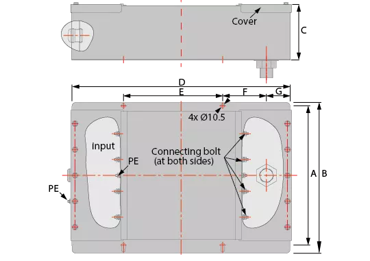
Outline drawing 3
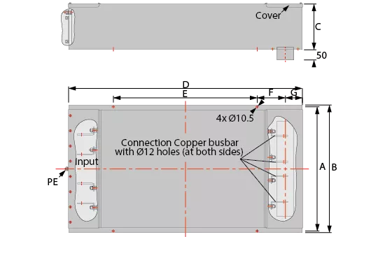
Outline drawing 4
| Type | A | B | C | D | E | F | G | Installation instructions | Outline drawing | IR (A) | I Leakage (A)* | I Reactive (A) | Terminal connection | Shielding Effectiveness (dB) | ||
|---|---|---|---|---|---|---|---|---|---|---|---|---|---|---|---|---|
| In | Out | |||||||||||||||
| 8020-4-16 | 288 | 305 | 120 | 750 | 450 | 110 | 80 | M33 conduit screw | 3 | 4 x 16 | 0.005 | 1.7 | M6 screw | M6 screw | 100 dB, 14 kHz ~ 40 GHz |
|
| 8020-4-32 | 288 | 305 | 120 | 750 | 450 | 110 | 80 | M33 conduit screw | 3 | 4 × 32 | 0.005 | 1.7 | M6 screw | M6 screw | ||
| 8020-4-63 | 348 | 365 | 140 | 920 | 620 | 110 | 80 | M33 conduit screw | 3 | 4 × 63 | 0.005 | 1.7 | M6 screw | M6 screw | ||
| 8020-4-100 | 348 | 365 | 155 | 960 | 450 | 205 | 80 | M60 conduit screw | 3 | 4 x 100 | 0.05 | 7.0 | M12 screw | M12 screw | ||
| 8020-4-200 | 348 | 365 | 155 | 960 | 450 | 205 | 80 | M60 conduit screw | 3 | 4 × 200 | 0.05 | 7.0 | M12 screw | M12 screw | ||
| 8020-4-250 | 536 | 556 | 205 | 1360 | 850 | 170 | 120 | 4 | 4 × 250 | 0.08 | 7.0 | Bus bar | Bus bar | |||
| 8020-4-400 | 670 | 690 | 225 | 1300 | 800 | 170 | 105 | 4 | 4 × 400 | 0.1 | 7.0 | Bus bar | Bus bar | |||
| 8020-4-630 | 900 | 920 | 255 | 1450 | 900 | 185 | 115 | 4 | 4 × 630 | 0.1 | 7.0 | Bus bar | Bus bar | |||
| 8020-4-800 | 945 | 965 | 255 | 1450 | 900 | 185 | 115 | 4 | 4 × 800 | 0.12 | 7.0 | Bus bar | Bus bar | |||
| 8020-4-1000 | 910 | 930 | 275 | 1790 | 1150 | 270 | 125 | 4 | 4 x1000 | 0.12 | 7.0 | Bus bar | Bus bar | |||
| 8020-4-1200 | 910 | 930 | 275 | 1790 | 1200 | 280 | 110 | 4 | 4 x 1200 | 0.18 | 7.0 | Bus bar | Bus bar | |||
* If the voltage between neutral and earth is 0V Actual size may differ from the above. Please contact us for the correct size
Worldwide leading manufacturer of EMC (electromagnetic compatibility), EMI (electromagnetic interference) and RFI(radio frequency interference) shielding solutions. Our EMC/EMI specialists will work together with you from the design phase through final production.
Useful links
Contact
3316 BP Dordrecht
The Netherlands
VAT: NL008884912B01
Tel: +31(0)78 - 204 90 00
Contact us Opening hours: Monday until Friday - 8:30am-5:00pm CEST