- Contact Us
- |
- Jobs
- |
- About Us
- |
- |
-
- Personal information
- Organization
- Quotes
- Address book
- Login
- Don't have an account? Sign-up
EMI troubleshooting, step-by-step
- Home
- EMI troubleshooting, step-by-step
EMI troubleshooting, step-by-step
In this article, we will describe the steps we usually take to troubleshoot the top four EMI issues; conducted emissions, radiated emissions, radiated immunity, and electrostatic discharge.
"Article originally published in Interference Technology (https://interferencetechnology.com/emi-troubleshooting-step-step/) by Kenneth Wyatt”
In this article, we will describe the steps we usually take to troubleshoot the top four EMI issues, conducted emissions, radiated emissions, radiated immunity, and electrostatic discharge. Of these, the last three are the most prevalent issues, with radiated emissions typically being the number one failure. If your product or system (EUT) has adequate power and I/O port filtering, conducted emissions and the other power line-related immunity tests are not usually an issue.
For your convenience, we have developed a list of recommended equipment useful for troubleshooting EMI. The download link is listed in Reference 1.
Conducted Emissions
This is usually not an issue given adequate power line filtering, however, many low-cost power supplies lack good filtering. Some “no name” brands have no filtering at all! The conducted emissions test is easy to run, so here you go.
Set up your spectrum analyzer as follows:
- Frequency 150 kHz to 30 MHz
- Resolution bandwidth = 10 or 9 kHz
- Preamp = Off
- Adjust the Reference Level so the highest harmonics are displayed and the vertical scale is reading in even 10 dB increments
- Use average detection initially and CISPR detection on any peaks later
- Internal attenuation – start with 20 to 30 dB at first and adjust for best display and no analyzer overload.
- Set the vertical units to dBμV
We also like to set the horizontal scale from linear to log, so frequencies are easier to read out.
Obtain a Line Impedance Stabilization Network (LISN) and position it between the product or system under test and the spectrum analyzer. Note the sequence of connection below!
CAUTION: It’s often important to power up the EUT prior to connecting the LISN to the analyzer. This is because large transients can occur at power-up and may potentially destroy the sensitive input stage of the analyzer. Note that the TekBox LISN has built-in transient protection. Not all do…you have been warned!
Power up the EUT and then connect the 50-Ohm output port of the LISN to the analyzer. Note the harmonics are usually very high at the lower frequencies and taper off towards 30 MHz. Be sure these higher harmonics don’t overdrive the analyzer. Add additional internal attenuation, if required.
By comparing the average detected peaks with the appropriate CISPR limits, you’ll be able to tell whether the EUT is passing or failing prior to formal compliance testing.
Ambient Transmitters
One problem you’ll run into immediately when testing outside of a shielded room or semi-anechoic chamber, is the number of ambient signals from sources like FM and TV broadcast transmitters, cellular telephone, and two-way radios. This is especially an issue when using current probes or external antennas. We’ll usually run a baseline plot on the analyzer using “Max Hold” mode to build up a composite ambient plot. Then, We’ll activate additional traces for the actual measurements. For example, we often have three plots or traces on the screen; the ambient baseline, the “before” plot, and the “after” plot with some fix applied.
Often, its easier to narrow the frequency span on the spectrum analyzer down to zero in on a particular harmonic, thus eliminating most of the ambient signals. If the harmonic is narrow band continuous wave (CW), then reducing the resolution bandwidth (RBW) can also help separate the EUT harmonics from nearby ambients. Just be sure reducing the RBW doesn’t also reduce the harmonic amplitude.
Another caution is that strong nearby transmitters can affect the amplitude accuracy of the measured signals, as well as create mixing products that appear to be harmonics, but are really combinations of the transmitter frequency and mixer circuit in the analyzer. You may need to use an external bandpass filter at the desired harmonic frequency to reduce the affect of the external transmitter. Although more expensive, an EMI receiver with tuned preselection would be more useful than a normal spectrum analyzer in high RF environments. Keysight Technologies and Rohde & Schwarz would be suppliers to consider. All these techniques are described in more detail in Reference 3.
Radiated Emissions
This is normally the highest risk test. Set up your spectrum analyzer as follows:
- Frequency 10 to 500 MHz
- Resolution bandwidth = 100 or 120 kHz
- Preamp = On (or use an external 20 dB preamp if the analyzer lacks this)
- Adjust the Reference Level so the highest harmonics are displayed and the vertical scale is reading in even 10 dB increments
- Use positive peak detection
- Set the internal attenuation = zero
Sometimes I prefer setting the vertical units from the default dBm to dBμV, so the displayed numbers are positive. This is also the same unit used in the test limits of the standards. I also like to set the horizontal scale from linear to log, so frequencies are easier to read out.
I perform my initial scan up to 500 MHz, because this is usually the worst case band for digital harmonics. You’ll want to also record the emissions at least up to 1 GHz (or higher) in order to characterize any other dominant emissions. Generally speaking, resolving the lower frequency harmonics will also reduce the higher harmonics.
Near Field Probing
Most near field probe kits come with both E-field and H-field probes. Deciding on H-field or E-field probes depends on whether you’ll be probing currents – that is, high di/dt – (circuit traces, cables, etc.) or high voltages – that EMI is, dV/dt – (switching power supplies, etc.) respectively. Both are useful for locating leaky seams or gaps in shielded enclosures.
Start with the larger H-field probe (Figure 1) and sniff around the product enclosure, circuit board(s), and attached cables. The objective is to identify major noise sources and specific narrow band and broadband frequencies. Document the locations and dominant frequencies observed. As you zero in on sources, you may wish to switch to smaller-diameter H-field probes, which will offer greater resolution (but less sensitivity).
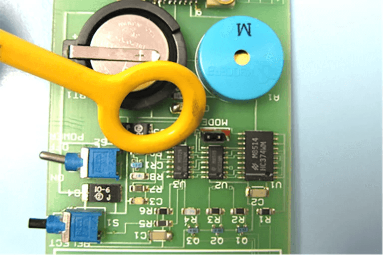
Figure 1. A near field probe is used to help identify potential sources of emissions.
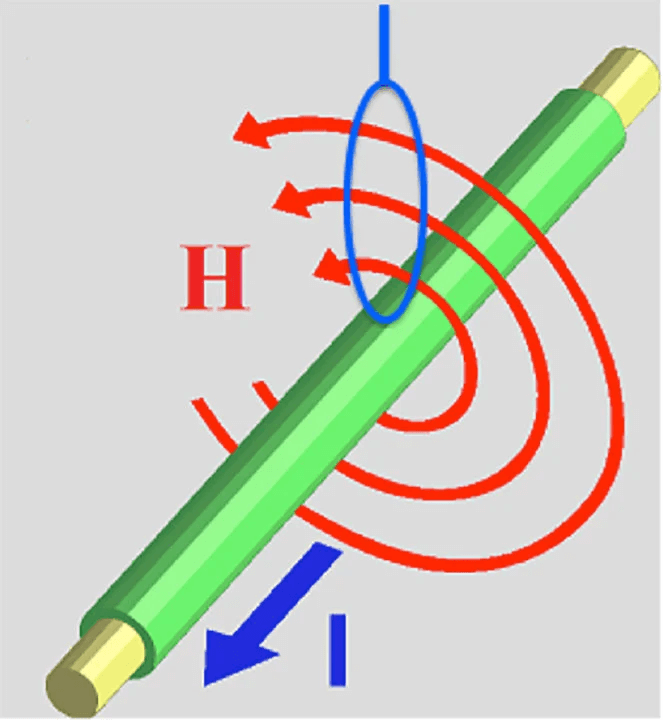
Figure 2. H-field probes offer the best sensitivity when oriented in relation to the circuit trace or cable, as shown. Figure, courtesy Patrick André.
Remember that not all sources of high frequency energy located on the board will actually radiate! Radiation requires some form of coupling to an “antenna-like” structure, such as an I/O cable, power cable, or seam in the shielded enclosure.
Compare the harmonic frequencies with known clock oscillators or other high frequency sources. It will help to use the Clock Oscillator Calculator, developed by my co-author, Patrick André. See the download link in Reference 2.
When applying potential fixes at the board level, be sure to tape down the near field probe to reduce the variation you’ll experience in physical location of the probe tip. Remember, we’re mainly interested in relative changes as we apply fixes.
Also, H-field probes are most sensitive (will couple the most magnetic flux) when their plane is oriented in parallel with the trace or cable. It’s also best to position the probe at 90 degrees to the plane of the PC board. See Figure 2.
Current Probe Next, measure the attached common mode cable currents (including power cables) with a high frequency current probe, such as the Fischer Custom Communications model F-33-1, or equivalent (Figure 3). Document the locations of the top several harmonics and compare with the list determined by near field probing. These will be the most likely to actually radiate and cause test failures, because they are flowing on antenna-like structures (cables). Use the manufacturer’s supplied calibration chart of transfer impedance to calculate the actual current at a particular frequency. Note that it only takes 5 to 8 μA of high frequency current to fail the FCC or CISPR test limits.
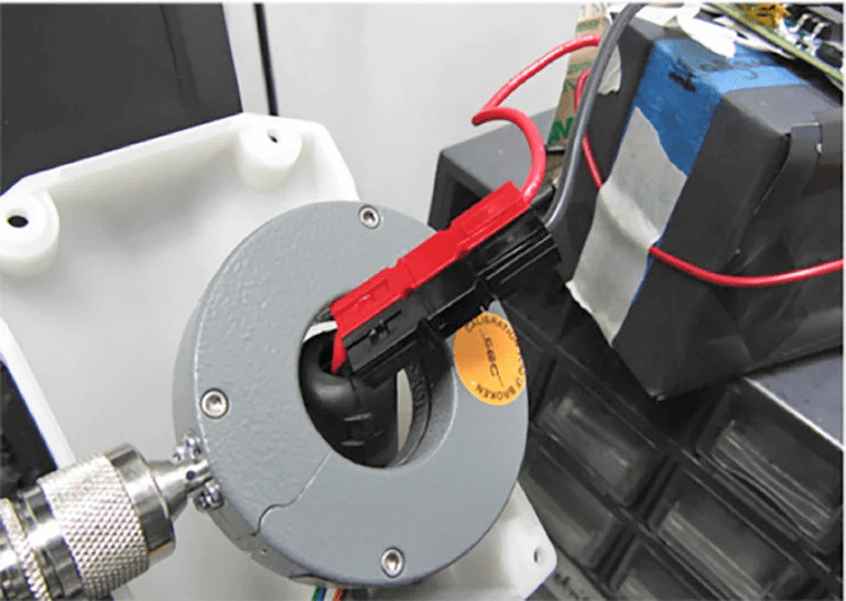
Figure 3. Use of a current probe to measure high frequency currents flowing on I/O and power cables.
It’s a good idea to slide the current probe back and forth to maximize the harmonics. This is because some frequencies will resonate in different places, due to standing waves on the cable.
Its also possible to predict the radiated E-field (V/m) given the current flowing in a wire or cable, with the assumption the length is electrically short at the frequency of concern. This has been shown to be accurate for 1m long cables at up to 200 MHz. Refer to Reference 3 for details.
Note on the Use of External Antennas
Note that there are two distinct goals when using external EMI antennas;
- Relative troubleshooting , where you know areas of failing frequencies and need to reduce their amplitudes. A calibrated antenna is not required, as only relative changes are important. The important thing I that harmonic content from the EUT should be easily visible.
- Pre-compliance testing, where you wish to duplicate the test setup as used by the compliance test lab. That is, setting up a calibrated antenna 3m or 10m away from the product or system under test and determining in advance whether you’re passing or failing.
Pre-Compliance Testing for Radiated Emissions
If you’re desiring to set up a pre-compliance test, (#2 above), then given a calibrated EMI antenna spaced 3m or 10m away from the EUT, you can calculate the E-field (dBμV/m) by recording the dBμV reading of the spectrum analyzer and factoring in the coax loss, external preamp gain (if used), any external attenuator (if used), and antenna factor (from the antenna calibration provided by the manufacturer). This calculation can then be compared directly with the 3m or 10m radiated emissions test limits using the formula:
E-field (dBμV/m) = SpecAnalyzer (dBμV) – PreampGain (dB) + CoaxLoss (dB) + AttenuatorLoss (dB) + AntFactor (dB)
For the purposes of this article, I’ll focus mainly on the procedure for troubleshooting using a close-spaced antenna (#1 above) for general characterization of harmonic levels actually being radiated and testing potential fixes. For example, knowing you may be over the limit by 3 dB at some harmonic frequency means your goal should be to reduce that emission by 6 to 10 dB for adequate margin.
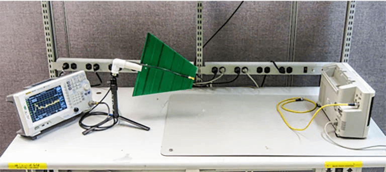
Figure 4. A typical test setup to measure actual radiated emissions while troubleshooting the causes.
Troubleshooting with a Close-Spaced Antenna
Once the product’s harmonic profile is fully characterized, it’s time to see which harmonics actually radiate. To do this, we use an antenna spaced at least 1m away from the product or system under test to measure the actual emissions (Figure 4). Typically, it will be leakage from attached I/O or power cables, as well as leakage in the shielded enclosure. Compare this data to that of the near field and current probes. Can you now determine the probable source(s) of the emissions noted?
Try to determine if cable radiation is the dominant issue by removing the cables one by one. You can also try installing a ferrite choke on one, or more, cables as a test. Use the near field probes to determine if leakage is also occurring from seams or openings in the shielded enclosure.
Once the emission sources are identified, you can use your knowledge of filtering, grounding, and shielding to mitigate the problem emissions. Try to determine the coupling path from inside the product to any outside cables. In some cases, the circuit board may need to be redesigned by optimizing the layer stack-up or by eliminating high speed traces crossing gaps in return planes, etc. By observing the results in real time with an antenna spaced some distance away, the mitigation phase should go quickly.
Common Issues
There are a number of product design areas that can cause radiated emissions:
- Poor cable shield terminations is the top issue
- Leaky product shielding
- Internal cables coupling to seams or I/O areas
- High speed traces crossing gaps in the return plane
- Sub-optimal layer stack-up
Refer to the references for additional details on system and PC board design issues that can cause emissions failures.
Radiated Immunity
Most radiated immunity tests are performed from 80 to 1000 MHz (or, in some cases, as high as 2.7 GHz). Common test levels are 3 or 10 V/m. Military products can go as high as 50 to 200 V/m, depending on the operational environment. The commercial standard for most products is IEC 61000-4-3, whose test setup is quite involved. However, using some simple techniques, you can identify and resolve most issues quickly.
Handheld Radio For radiated immunity, we generally start outside the EUT and use license-free handheld transmitters, such as the Family Radio Service (FRS) walkie-talkies (or equivalent) to determine areas of weakness. By holding these low power radios close to the product or system under test, you can often force a failure (Figure 5).
Hold the transmit button down and run the radio antenna all around the EUT. This should include all cables, seams, display ports, etc.
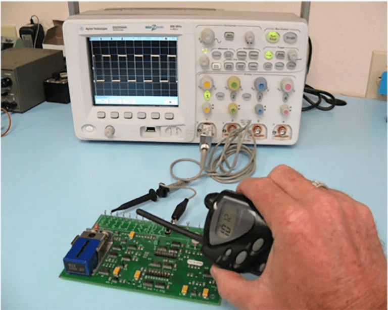
Figure 5. Using a license-free transmitter to force a failure.
RF Generator
It’s very common that only certain frequency bands are susceptible and sometimes the fixed frequency handheld radios are not effective. In that case, I use an adjustable RF generator with attached large size H-field probe and probe all around at known failing frequencies. It also helps to probe the internal cables and PC board to determine areas of sensitivity. For smaller products, as in Figure 6, try using the smaller H-field probes for best physical resolution.
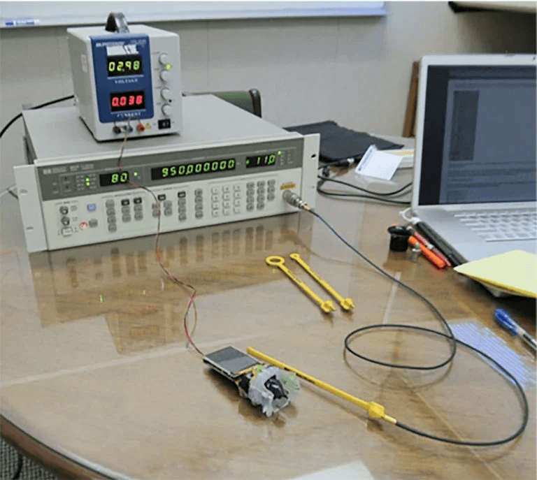
Figure 6. Using an RF generator and H-field probe to determine areas of sensitivity.
In place of the larger lab-quality RF generators, I also use a smaller USB-controlled RF synthesizer, such as the Windfreak SynthNV (or equivalent) with the near field probe. The SynthNV can produce up to +19 dBm RF power from 34 MHz to 4.4 GHz, so works well. This also fits into my EMI troubleshooting kit nicely. See Figure 7. You’ll find a list of recommended generators in Reference 1.
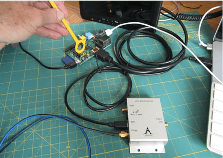
Figure 7. Using a small synthesized RF generator to produce intense RF fields around the probe tip
Electrostatic Discharge
Electrostatic discharge testing is best performed using a test setup as described in the IEC 61000-4-2 standard. This requires a test table and ground planes of certain dimensions. The EUT is placed in the middle of the test table. I usually suggest replacing floor tiles with copper or aluminum 4 x 8-foot sheets, which will fit right into the spaces of the existing tiles (Figure 8). Testing requires an ESD simulator, which is available from a number of sources. See Reference 1. I use the older KeyTek MiniZap, which is relatively small and can be adjusted to +/- 15 kV. There are several other suitable (and newer) designs.
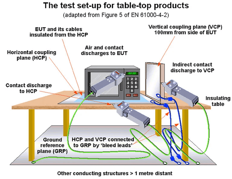
Figure 8. The ESD test setup according to IEC 6100-4-2. Image, courtesy Keith Armstrong.
ESD testing is rather complex as far as identifying the test points, but basically, there are two tests – air discharge and contact discharge. Use air discharge for all points where an operator could touch the outside of the EUT. Use contact discharge for all exposed metal where an operator could touch and discharge into. Test both positive and negative polarities. Most commercial tests require 4 kV contact discharge and 8 kV air discharge.
The test setup also includes horizontal and vertical coupling planes. Use the contact discharge tip into the coupling planes. These planes need a high-impedance discharge path to earth. See the IEC standard for details and exact test procedures.
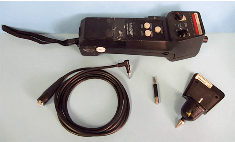
Figure 9. A typical ESD simulator with air and contact discharge tips. It can produce up to +/- 15 kV.
Summary
By developing your own EMI troubleshooting and pre-compliance test lab, you’ll save time and money by moving the troubleshooting process in-house, rather than scheduling time and the related cost and scheduling delays by depending on commercial test labs.
Most of the high-risk EMI tests are easily performed with low-cost equipment. The cost savings by performing troubleshooting at you own facility can mount up to hundreds of thousands of dollars and weeks or months of product delays.
References
Recommended list of EMI troubleshooting equipment – http://www.emc-seminars.com/EMI_Troubleshooting_Equipment_List-Wyatt.pdf
- Clock Oscillator Calculator (Patrick André) – http://andreconsulting.com/Harmonics.xls
- André and Wyatt, EMI Troubleshooting Cookbook for Product Designers, SciTech, 2014.
- Joffe and Lock, Grounds For Grounding, Wiley, 2010
- Ott, Electromagnetic Compatibility Engineering, Wiley, 2009
- Mardiguian, EMI Troubleshooting Techniques, McGraw-Hill, 2000
- Montrose, EMC Made Simple, Montrose Compliance Services, 2014
- Morrison, Grounding And Shielding – Circuits and Interference, Wiley, 2016
- Williams, EMC For Product Designers, Newnes, 2017
