- Contact Us
- |
- Jobs
- |
- About Us
- |
- |
-
- Personal information
- Organization
- Quotes
- Address book
- Login
- Don't have an account? Sign-up
Active compensation systems
- Home
- Mu-Metal - Magnetic shielding materials
- Active compensation systems
System to reduce magnetic fields.
Reducing magnetic fields in the 0 Hz range can in some cases be solved with Low-frequency magnetic shielding (MuFerro), Prefabricated and modular faraday cages, Mu-ferro HD. Generally speaking an expensive solution.
For the low-frequency fields in the 10-500 Hertz frequency range, in some cases, we can do this with active compensation. We do this with correction coils around the area where the magnetic field has to be corrected. These coils are quite big in size, about 5 times the length of the correction area. This is to create a homogeneous field where the gradient is nearly equal everywhere.
Near to the sensor, the reduction factor can even be up to 100 times, depending on the homogeneity of the field. The geometry of the correction coils has an influence on the results too.
Applications
- electron microscopes
- x-ray equipment
Generally speaking, this is not the ideal system for EMG and ECG rooms, due to high cost and higher energy consumption. We can tune the system on specific frequencies.
To prevent instabilities we always recommend to combine this with passive shielding.
We can create a contra-field for 0 Hz and low frequencies so that the measured field is compensated. To prevent instability, it is wishful to make this in combination with a shield.
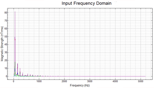
Up to 50 000 x reduction is possible. Depending on demand, shape, source and compensation volume
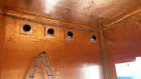
A lightweight magnetically shielded room with active shielding
Active compensation of the remnant magnetic field using a field mapping method.
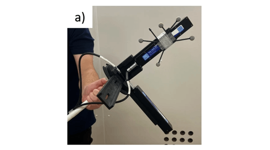
(a) Two tri-axial fluxgate magnetometers attached to a plastic stick. A series of five infrared reflective markers are also attached to the stick allowing optical tracking of the position and orientation of the sensors within the MSR.
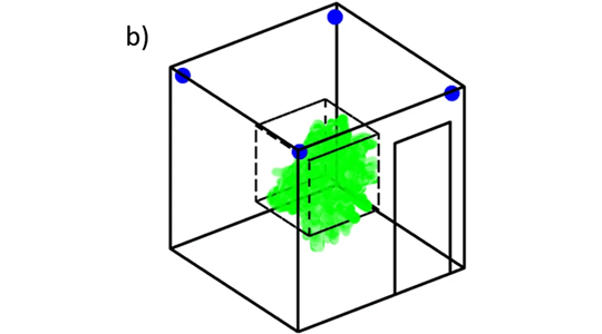
(b) Schematic of the field mapping setup. The tracking cameras are mounted in the corners of the MSR and highlighted in blue. The dashed black volume shows the central cubic metre volume within which the stick was moved. The green highlighted marks show the path which the fluxgate magnetometers followed during the field mapping process, covering most of the central cubic metre of the MSR.
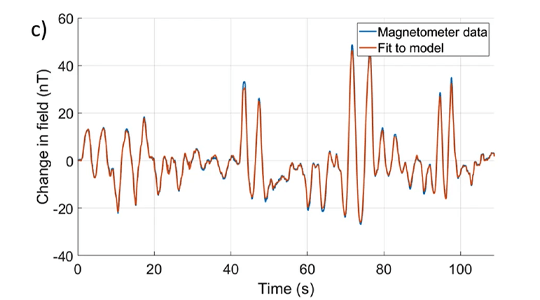
(c) Magnetometer data from a single component of one triaxial sensor measured when a single coil was activated. By combining the data from all magnetometers with the optical tracking data a spherical harmonic model can be used to approximate the strength and spatial variation of the field produced by each coil.
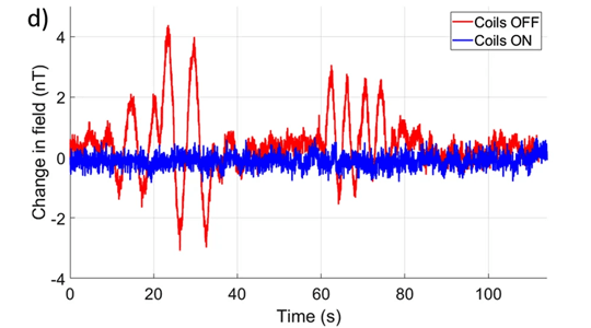
(d) The red trace shows the magnetic field measured by one magnetometer in the MSR with all coils switched off. The magnetic field model of each coil was used to calculate coil voltages which produce the required nulling field. Once voltages had been applied, the mapping was performed again. The blue trace shows the magnetometer data after nulling where similar sensor translations and rotations produce little to no change in the measured field.
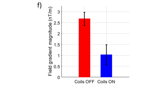
(e) Field mapping and nulling was repeated 8 times. The bar chart shows a consistent remnant field following demagnetisation and a consistent reduction in the RMS magnitude of the three uniform field components found by the model when the compensation is applied.

(f) A similar reduction is seen in the RMS magnitude of the five field gradient components.
